Introduction of DALI Dimming and its Advantages and Disadvantages
DALI is very flexible and makes it possible to create different groups that can be controlled separately with easy wiring. DALI's flexibility also brings with it that specialised knowledge is required for installing and commissioning. DALI is a bidirectional protocol which makes for easier commissioning and greater flexibility in control gear – for instance infrared presence sensors and light sensors.
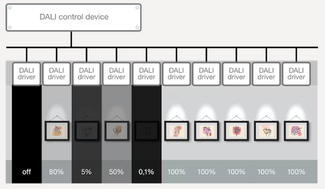
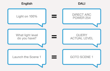
The DALI name is an acronym for Digital Addressable Lighting Interface. DALI is a digital lighting protocol and is mainly used for general lighting. DALI is a language for controllers and luminaires like English is a language for people.
DALI is used mainly in general lighting applications like office lighting, museum lighting and hospital lighting. DALI is a very flexible system and can control lighting systems with only one controller and one luminaire, or advanced systems with several lighting groups.
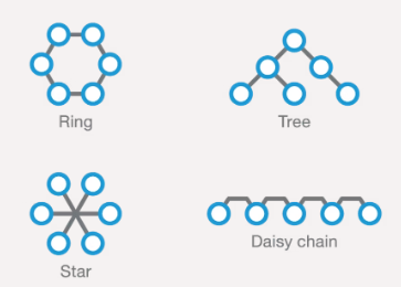
Another benefit is that the bus topology of a DALI installation is very flexible. Bus, daisy-chain, mesh and star are all valid topologies.
What Is Topology?
Topology is the way devices are connected in a network. Some examples are:
- Daisy-chain: each device is connected only to the previous and next device in the network
- Star: each device is connected to one central master device only
- Tree: is like a daisy chain, but can have branches
- Ring: is also like a daisy chain, but with improved redundancy if a part of the chain fails
When Should I Use DALI?
Use DALI when flexibility is needed in your system. For instance, when different groups of light must be able to be set at different brightness levels. DALI is also a bidirectional system – the controlled lighting group gives feedback to the DALI controller about its state, like current brightness level. Bidirectional communication can also be used for light sensors and presence detectors.
DALI Advantages
− Open IEC standard (IEC 62386) and can be used by anyone
− DALI has an active organisation and DALI is constantly improved and extended
− Full digital control – group creation or individual control of fixtures.
− Bi-directional communication makes for easier commissioning and greater flexibility in control gear.
− Polarity independent two wire control.
− BUS based protocol.
− Standardized dimming curves – better compatibility between controllers and LED drivers.
DALI Disadvantages
− Maximum 64 clients per controller
− Slow – less suitable for fast brightness changes
− Specific knowledge is required during commissioning
− Hardware and software commissioning is required
− Only 254 digital values (from 0-100%) gives low dimming resolution
Difference Between DC 1-10V and 0-10V Dimming Methods
DC 1-10V: 
The principle of DC1-10V dimming is a method controlling output of the driver is 100% fully on in case the dimming signal given is 10V or just simply make the dimming wires open, while output level is set at 10% in case the dimming signal is given at 1V.
100% is the maximum of driver and 10% is the minimum level. The dimming response can be found in the figure below.
The output status is not guaranteed when the dimming signal is less than 1V or even short the dimming wires. The output of LED driver could be completely switched off or there is still some light coming out of LED module. In case application would require to completely turn off the driver, one switch at AC mains of driver is required.
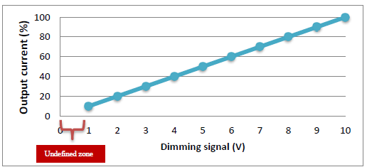
DC1-10V Output vs Dimming input
DC 0-10V:
The maximum output level is still 100% in case the dimming signal is given at 10V or open the dimming wires.
However, the minimum level for DC0-10V is 5.7% in case the dimming signal is given at 0.57V. In case the dimmer is given lower than 0.57V or users just short the dimming wires, the LED driver will cut off the output current resulting no light output in the LED module.
The dimming response can be found in the figure below.
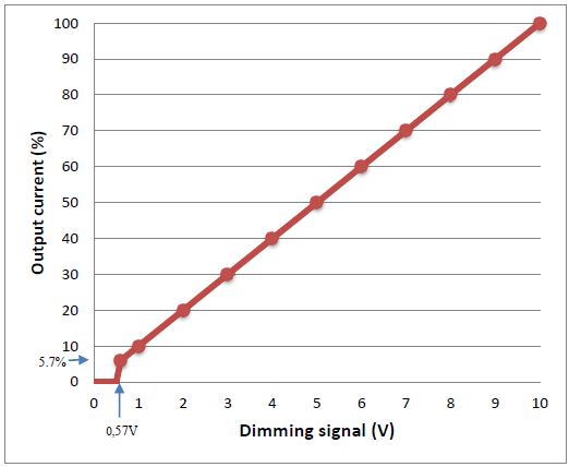
DC0-10V Output vs Dimming input
Summary:
DC 0-10V is considered as the second generation of dimming method providing the minimum dimmable level 5.7% and output level zero(output completely switch off guaranteed) in case the input signal is less than 0.57V. The table in below shows the comparison.
|
Output Level
|
Maximum(%) | Minimum(%) |
Dimming Signal < 5.7V
|
Dimming Wires Shored |
|
DC1-10V
|
100 | 10 |
Not Defined
|
Not Defined |
|
DC0-10V
|
100 | 5.7 | 0 | 0 |
Introduction of DMX Dimming and its Advantages and Disadvantages
DMX
DMX is a digital protocol and is typically used for dynamic colour lighting systems. Originally, DMX is used for stage lighting in theatres and concerts, but it is also widely used for architectural lighting.
DMX is a unidirectional protocol. This means that the DMX controller only sends signals to the driver – the driver cannot send signals to the controller. However, the protocol enhancement RDM is developed, which adds bidirectional communication to DMX.
The Protocol
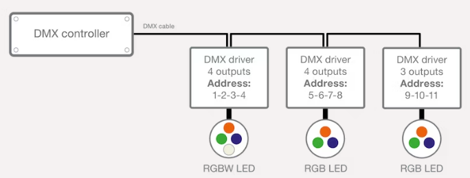
A DMX controller sends messages to each device in its network. The protocol sends a value between 0 and 255 to each of the 512 channels. For example: The value can be used to set a light level, but also to set the position of a moving head or to change gobo's.
One device can use multiple channels. For example, a four channel LED driver assigned to channel 5 will also use channels 6, 7 and 8 – one channel for each colour. Even if only three outputs are connected as the middle driver in figure 8.
RDM
RDM adds bidirectional communication to DMX. This is especially useful during commissioning. Without RDM, a channel must be assigned to each device. And if a channel must be changed of a device hanging high above the stage in a theatre, someone has to go to that device physically to change its channel. With RDM, channels can be assigned automatically by the controller, without the need to program each device separately.
When to Use DMX?
DMX is developed for use with dynamic coloured lighting. Use it for stage lighting, colour architectural lighting, or all other projects with dynamic coloured lighting.
Wiring
DMX uses three signal wires plus mains wiring. The maximum cable length is 300 meters from the controller to the last driver. Every 32nd driver needs a repeater and the last driver in the system needs a termination resistor of 120Ω.
DMX uses EIA-485 (RS-485) rated cable or CAT5E Ethernet cable.
Advantages of DMX
− Standardized protocol (USITT DMX512-A) and based on RS-485
− Made for color dynamics, but also for sound & moving heads
− Fast – suitable for highly dynamic light shows
− One DMX universe can handle 512 individual addresses
− Large distance possible between the controller and the last driver (up to 300 meters)
Advantages of DMX/RDM
− No need to program the driver individually – can be done via the RDM controller
− Possibility to report status of connected devices
Disadvantages of DMX and DMX/RDM
− Complex – specialised knowledge is needed
− Special cables required for control signals (EIA-485 or CAT5E)
− Individual programming of drivers is needed (not with RDM)
PIR and Microwave Sensor, Which Suit Your Needs?
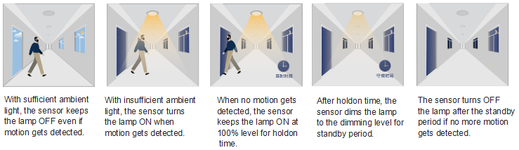
Lighting can now incorporate sensors to make them even more effective. Motion detectors can now be used to pick up when someone approaches so the lamps are triggered when they are needed. This can be used to save on energy bills by dimming or turning off the lamps when no one is around, or it can be used as a security measure, with lamps coming on to let you know when someone approaches.
There are two main types of motion detection sensors available, microwave and PIR (Passive Infrared) and we’re here to take a quick look at the pros and cons of each.
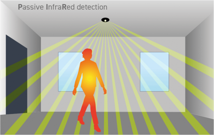
PIR Sensor
The sensor detects heat. They do this by measuring the ambient temperature of the room using several detection beams. When a difference in temperature is detected by one of the beams, the sensor is activated, switching on the lamps. When all the beams sense the same temperature again, the lamps will switch off.
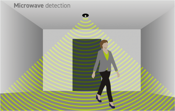
Microwave Sensor
The motion detector emits microwave signals and measure the time taken for the signal to be reflected back to the sensor, this is known as the echo time. The echo time is used to calculate the distances from all the stationary objects in the detection zone, to establish a baseline to work from. A person moving into the detection zone causes a disruption in the microwave beam, changing the echo time and triggering the lamps.
Coparision
| PIR | Microwave | |
| Sensitivity | Under sensitive in higher background temperatures. Over sensitive in lower temperatures. | Consistent detection over all temperatures. |
| Coverage | 90° | 360° |
| Detection | Can be insensitive when walking directly towards the sensor | Can sense movement through walls |
Since PIR sensor uses the difference in heat to detect movement, ambient temperatures can greatly affect sensitivity. This limitation should be considered if you are looking at motion detection systems for outdoor lighting. The more extreme temperatures of outdoors can have a significant impact on devices’ effectiveness. On the other hand, microwave sensors may struggle more with smaller indoor spaces. Because they are able to detect movement through walls, they can be overly sensitive and be triggered by movement you might not want it to be.
3-step Dimming with 1-10V Dimmable LED Driver
Photocells are variable resistors that adjust the resistance in an electrical circuit based on the level of light present in their mounted location. To function properly, they need to be placed in exposed areas where they can receive sufficient light. Photocells, also known as photo controls, come in various shapes and sizes and can be integrated into a luminaire or added as an accessory, depending on the specific light fixture.
Photocell Sensor
A photocell senses when the sun is setting or rising and turns fixtures, such as outdoor street lamps, on or off based on the time of day. Like many other sensor technologies, photo controls help save energy and money when paired with outdoor light fixtures in various industrial, commercial, and residential applications.
Most of these sensors have a dusk-to-dawn feature which automatically turns the light on when the sun goes down and turns them off when the sun rises, so you don't need to worry about remembering.
Photocell Controller
Unlike the photocell sensor that turns on or off the lamp fixtures according to the ambient light level, the photocell controller dims up and down the fixtures automatically in a smooth manner. This is virtually a more precise light control, resulting in more consistent light level and thus comfortable visual experience.
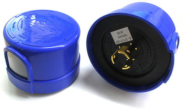
NEMA Socket
NEMA socket provides an electrical and mechanical connection between the control cell and the luminaire. ANSI C136 coded standard clearly defines the size of the socket, the type of locking and other details, the socket is a standardized type of connection across the lighting industry.
The socket in light fixtures may have 5 or 7 terminals. 3 terminals used for power connection, the remaining 2 or 4 terminals are used to carry dimming signal and other signals. The power terminals can carry current up to 15A. The signal terminals are limited to 100mA.
NEMA socket signal contacts can support the 1-10VDC or Digital Addressable Lighting Interface (DALI) protocol. Intelligence lighting systems which allows remote monitoring, control can be easily attached to any light fixture when produced in accordance with NEMA socket structure.
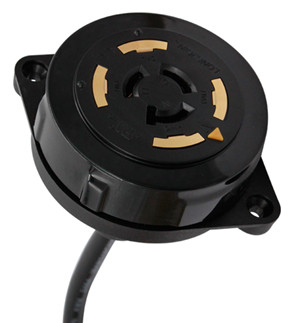
Shorting Cap
In many commercial applications, such as parking lots and area lighting, photocells are externally mounted using a twist-lock socket or adapter. By replacing the photocell with a shorting cap, the circuit in the LED light fixture is closed, keeping the light in an always-on state. This allows for external control if a central photocell or switch system is being used.
The shorting cap is also intend to short a twist-lock photocontrol receptacle while under maintenance.
Tips for Using Photocells
If you live in the northern hemisphere, your light sensors should face the north. If the sensor faces east, it will turn on and off early. If it faces west, it will turn on and off late. Due to the way the sun arcs, southern facing photocells are exposed to too much. Exposing sensors to too much direct sunlight can cause premature failure and burn out the components. If direct north isn't an option, point your photocells northeast or northwest depending on if you'd prefer the light to come on earlier in the day or stay on later.
When selecting a photocell to use with LED light fixtures, be sure to check the sensor is LED compatible. Using a conventional photo control with LEDs can lead to premature system failure, or the sensor will not recognize the fixture and fail to work at all.